

bpribadi
-
Content Count
820 -
Joined
-
Last visited
Posts posted by bpribadi
-
-
Realise there isn't a pic of the tin. This pic is of my second CMOY, since torn apart. Instead of a volume pot, I used a switch to set the gain. Not a good idea, the difference in volume was not as expected.Nice work and photography!
-
BTW bpribadi, you are building a PPA right? Did you buy the board from Tangent or rolling your own? Also have you tried your AD8610s yet? I got two of them as samples, wondering if they will give me two more.Hi Heady,
I haven't start to build the PPA yet. I'm going to use matrix PCB for my project
 I know it is a bad habbit, but old habbit die hard, and I'm too lazy to learn Protel etc. to make a good printed PCB. Anyone willing to print me the PCB ?
 And I also going to have the LM6171 in it, so still building the test board for the LM6171 (60% populated) to prove my concept. So the PPA for general use, and the LM6171 headphone output will be for different flavor of sound.
The reason I don't buy PPA PCB is because of the fuse protection for the buffers. I'm going to protect all of them with fuses, so not possible using the PPA 1.1 board. Must wait until they accept my idea and make a new board

http://www5.head-fi.org/forums/showthread.php?t=80246
-
Are those Q1 - Q4 used to increase the output current ?
Pretty amp

-
Well, the big components will be the caps. IC and resistors are small. But small cap doesn't give good sound, so consider that

-
Hi, my friend is looking for Sony SACD player XA3000ES. Beside the online channel, anybody know cheaper place to buy this player?
Thanks!
-
Hi Starhushz,
Well, for low current audio signal, the effect is very minimum, so I normally use cooper wire for internal jumpering. CAT5 cable is good and cheap, I found that it sounds good. For cables, use OFC with shield (coaxial).
For high current such as speaker cable, then you need good cable to make them sound good.

Bram
-
Hi Starushz,
CMoy is the basic Non-Inverting configuration for an Op-Amp. So how good it is will be depend on the Op-Amp. Good power supply design, like design with buffer on the ground, will help to improve the sound performance.
A47 is Non-Inverting with additional buffer on the output to increase the output current. But personally I don't really like A47 because of a few reason:
1. Output resistors is necessary to minimize current flowing between the two outputs (output of the amplifier, and output of the buffer). These resistors will increase the output impedance. The ideal output impedance is 0 ohm, so high output impedance is not good, as it will reduce the damping factor, especially for low impedance headphone.
2. The buffer is not in parallel nor series. Means that the ouput of the buffer will have slight delay compare to the output of the amplifying op-amp, this will cause phase different.
So to my opinion, CMoy is better, if you use good op-amp with sufficient output current for the headphone. But for simple CMoy, remember to use JFET input op-amp such as OPA2134 to avoid output voltage offset.
There are other designs, but for first timer, I suggest to build a CMoy. I prefer to use the good components at the first time, because you want to be impressed with what you have made
 And to change cheapo components to a good one will waste more money and time. They are not so expensive anyway
 Happy DIY
But be carefull, it's gonna be addictive, especially for me 
-
Waiting for your comments of Pimeta

Just remember to turn off your amp before plug in or out the headphone jack. HA3-5002 doesn't have output protection, so becarefull with it
-
Will help the isolation I think, so bass will be improved, but not sure whether the treble will affected or not.
Please comment if you have tried it
How much is it? -
Wow, I never seen that casing in SLT. Looks solid and profesional
I think I haven't browse SLT well enough.Thanks for the info guys! I will try Martin and Bytetron to see what they have
-
Wow
Cool stuff !!! Thanks for sharing!Do you have it ? I wonder how it sounds
Does it have digital input?
-
Try get alu casing. They are cheaper and easy to drill.Yeap! Alu is easier
The stainless steel casing shown above has 3mm alu panel for front and back.You'd be surprised. I bought a nice case from SLT for $29. It's like a small rackmount chassis about D32cm * W22cm * H10cm. Powder coated black and with a 2mm thick steel faceplate too boot.May I know where did you get it from?
Thanks!
-
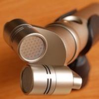
It's G2 with +10 dioptre B+W macro filter
-
Koba ElectronicsAddress : 101 Up Cross St #03-06 People's Pk Centre Singapore 058357
Telephone : 6533 1672
Thanks Sipher!
-
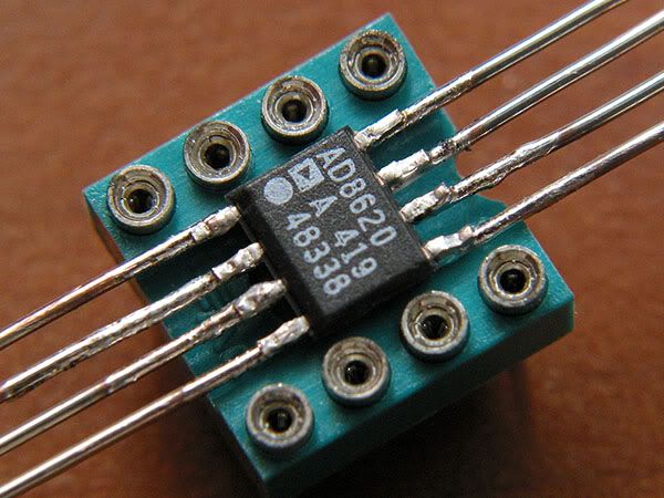
...the op-amp is actually "floating" above the IC holder cause the legs will shot each other if u solder them directly onto the holder, u'll need to build the "legs" on the IC holder first, good luckThanks tropicalrips!
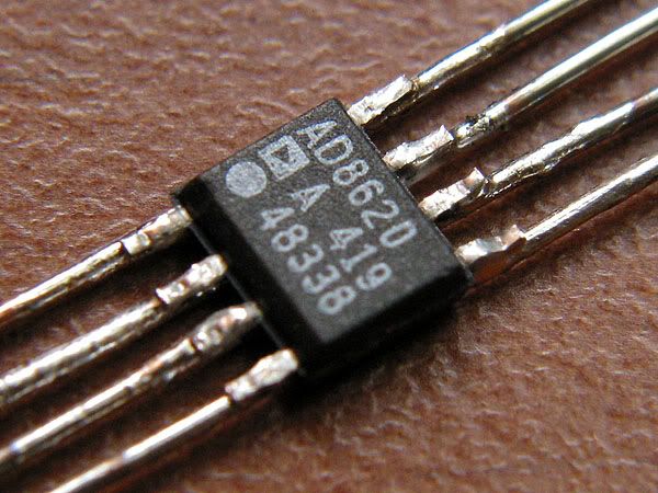
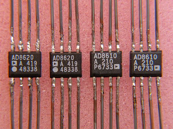
I just got those AD chips, wow, with TNT express, less than a week since ordering
Thanks a lot Analog Device !!!It was the most difficult soldering, and after an hour I found the technique, and after another 1.5 hours, here they are, ready to make music

I haven't put them in the 8 pin socket. I plan to make another CMoy with those AD8620s, so I think I will solder them directly to the PCB. That should make it sounds better isn't it
While the AD8610 is for my coming PPA For those who interested, I wrote how I did it here:
http://www.sgheadphones.net/index.php?showtopic=2476
-
Oooppss sorry to hear that... I just got mine for free from AD
They use TNT express for delivery, so it was less than a week from ordering till I got the chips.
Goosshh...
 it was the most difficult soldering I ever did. I tried few ways to make those ICs useable. At the end, the easiest way to do is to extend the legs.
So this is what I did:
1. Straighten all the chip legs with long nose plier.
2. grip them with my vise grip to make them steady (vise grip also help to transfer the solder's heat).
3. prepare a solid wire, not to big, 0.4 mm is good enough. Give a little bit of solder tin on the wire end.
4. Hold them steady, and let the wire end (already covered with solder tin) touch the chip leg, and heat the wire end with solder for a short time.
5. Done. Now the ICs are ready make music
Why don't you order some and try it
-
Well done heady! I love heatshrink to
Metal casing will help to reduce hum in some 'hum'full environment (like my office)
Or you can buy aluminum die cast from farnell (Hammond casing), then your CMoy will look more solid -
Thanks for sharing! Congratulations with your new CMoy
Can you give us a more detail of Koba Electronics address? It would be usefull for us
, thanks! -
Thanks guys! SLT has a lot of casings, but cheap and not nice. The components already cost more than SGD 300.-, so I'm not supposed to put it in SGD 10.- casing right?
Farnell has good casings, but also very expensive. The Hammond 1455 is nice and affordable, but not big enough for my project.
There one stainless steel casing from farnell, a bit bigger than what I need, pretty nice look, but cost around SGD 160.-
Here is the picture of the stainless steel casing:
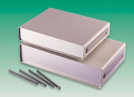
If possible I'm looking for good casing ranging around SGD 40 - 80 (max).
-
Thanks for the 'blabber'
I'dont really need isolation, since I don't listen to music in noisy area. Normally at home or in the office, so I still would like to hear when somebody call me
I will advice my friends to try KSC35.
-
Hi all,
I need a casing with dimension 20 x 25 cm (front panel 25 cm) and 5-6 cm height.
I want a nice one. Anybody know where to get those casing in Singapore?
I know digi can help, but he is in China, I can only see the casing from fotos, and payment also a bit difficult. I would like to inspect the casing before I buy it.
What is it for? Why so big?

I plan to build two headphone amps soon (for me and my brother). The circuitry drawing almost finalized.
It is a box with 2 headphone outputs and 1 pre out. No selector, so only one input.
The first output will come from PPA circuit design, with modified power supply and buffer protection. The fuses for buffer protection make the overall board big. I don't use PPA board, so I cannot call it PPA, probably Jung's Multiloop Non-Inverting will be a better name.
The second output will be from LM6171, a simple non-inverting with buffered input to make the input impedance match, to avoid output offset. The circuit is to be tested soon (it is my own idea, so I haven't seen people tried it yet).
The pre out will use the same circuit as LM6171, but independent. I heard from the forum LM6171 is a very good pre amp as well. To bad I don't have power amp to test it

It will be AC powered, with toroid transformer, so I need some space here.
Thanks for any advice!

Bram
-
Haiyaaa... why not just use a single op-amp chip
-
Still not a apple to apple comparison size wise
They are not clip-on or medium size diaphragm. They are large size So it is a small apple to big apple comparison For medium size (portable), do you know any other model that sounds good?
-
Wow !!!
Very neat !!!Did you use your C8080 to shoot those pics? If yes, your C8080 super macro is really good
Thanks for the tips! I will try it when the IC delivered.
Noobie help
in DIY Section
Posted · Edited by bpribadi · Report reply
I normally use Solen Caps for audio signal. They sound good and the price is reasonable. But they are a little bit bigger because they only available in high voltage.
You can buy them in Well Audio (Burlington Sq). The 0.47 uF cost SGD 2.4 (just as an example)
http://www.solen.ca/pics/polycaps.jpg
http://www.solen.ca/caps/mkp.htm
http://www.solen.ca/caps/mkp2.htm