


SvenMZ8
-
Content Count
45 -
Joined
-
Last visited
Posts posted by SvenMZ8
-
-
so what was the fault? ground channel opamp?
-
so ts fixed his mini^3 yet? din hear from him after i offered to help.
-
looks like u need a replacement clickwheel, or maybe the zif connector has loosen. i'll pm u a contact, he has most ipod parts but im not sure if he wld help u change the part.
good luck!
-
i got everything from sim lim tower and follow instructions from a library book from national library. its called "make" magazine.
-
yup. they look v nice!
-
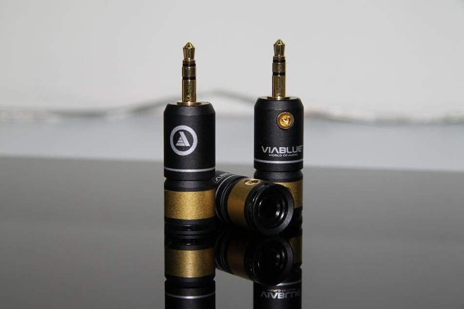
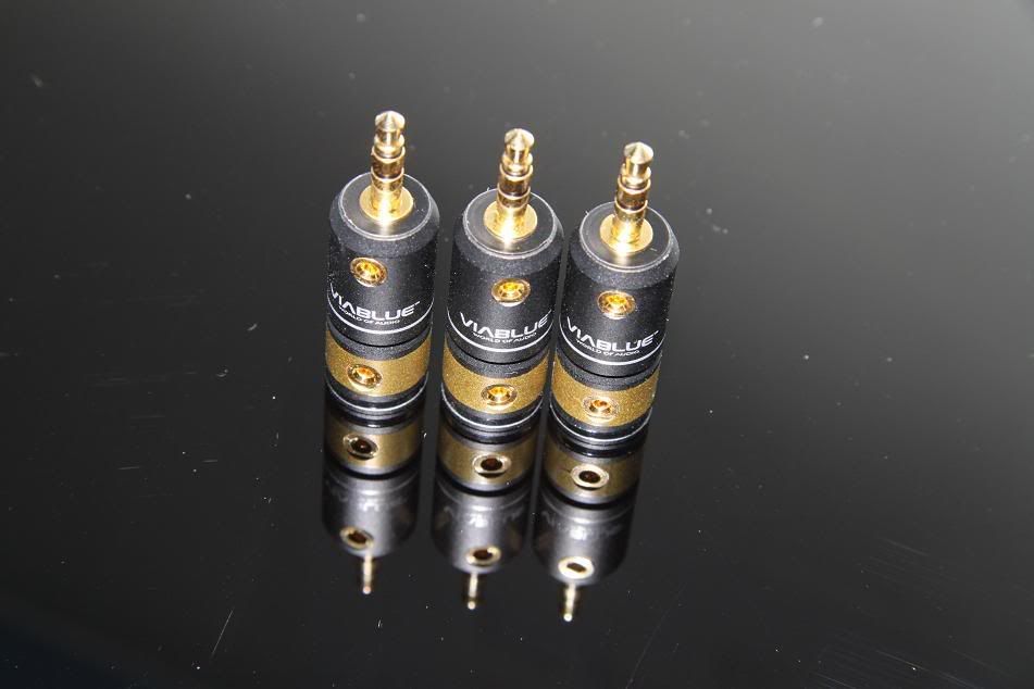
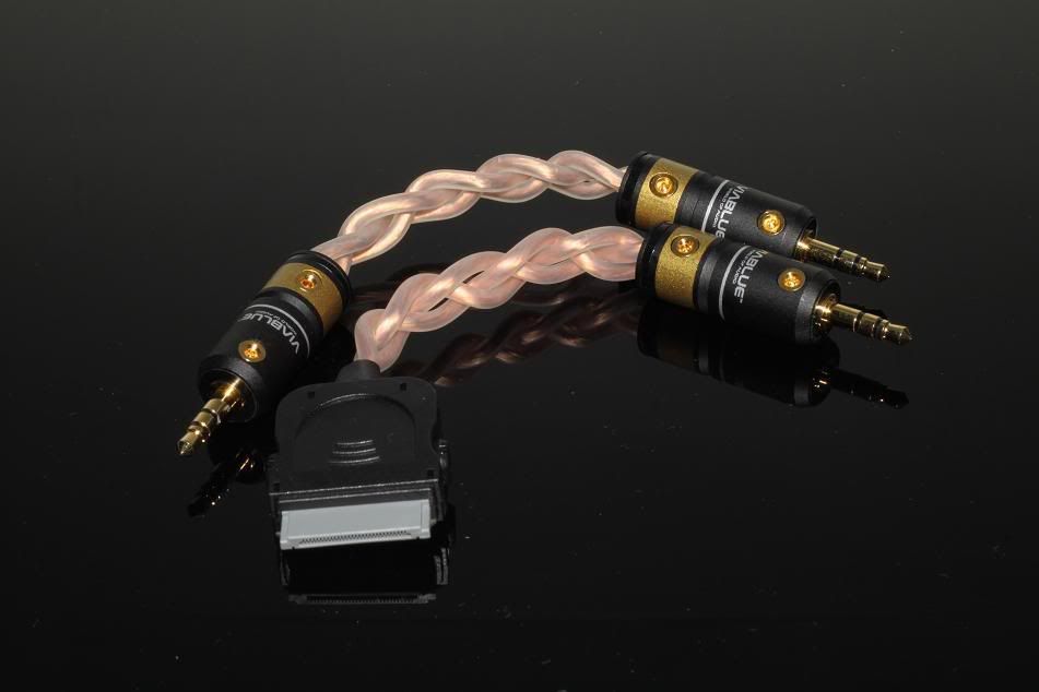
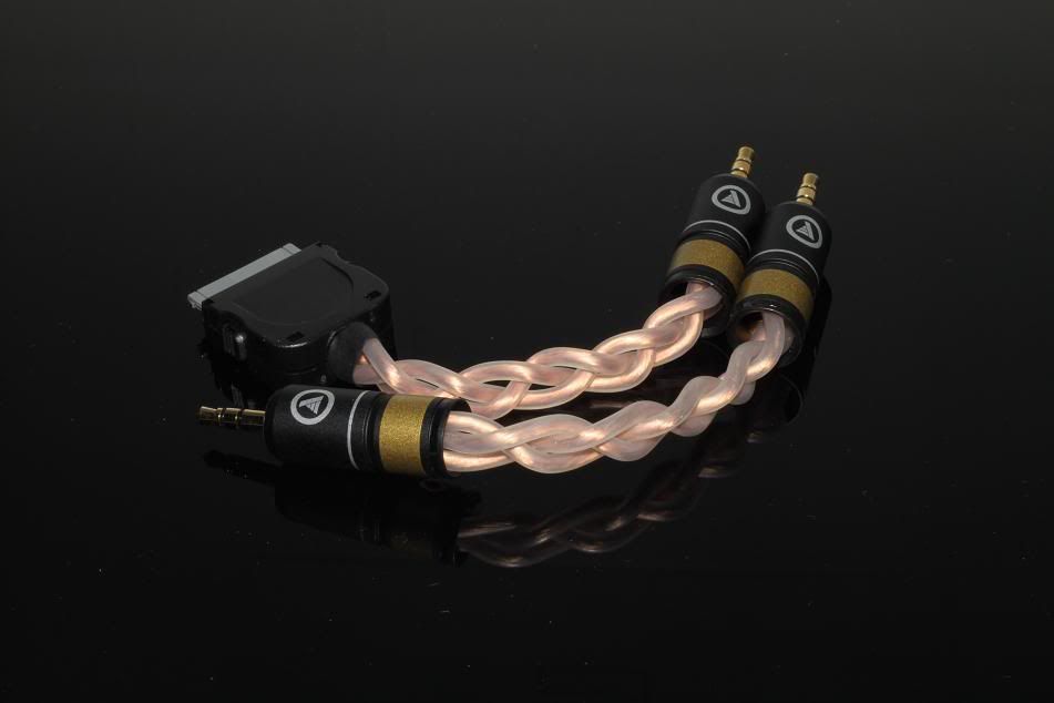
Some upgrades
Photos
-
Yes.
Slightly OT, but I'm quite tempted to pick up a 2nd-hand iPod, just to get the experience of opening it up.
if u do. pick up an iPod video 5th gen or 5.5th gen. try not get the classic as its very hard to pry open due to additional hinge clips inside.
-
something for u guys to try.
experiment one
say copper and silver cables in an interconnect.
one copper and one silver for all the three channels
but...add capacitors parallel across the copper and silver
ipod----------silver----------------amp
xxxxx | xxxxxxxxxxxxxxxxx |
xxxxx = xxxxxxxxxxxxxxxxx =
xxxxx | xxxxxxxxxxxxxxxxx |
xxxxx --------copper-------------
Note: Ignore the "x"s, they are there to counter the forum's post filtering, "=" sign is capacitor
this should add a delay, maybe allows the vocals or drum beats echo longer.
capacitor values can be experimented too.
---------------------------------------------------------------------------
experiment two
as u know there exist several blends of solder
-regular solder
-cardas eutentic
-mundorf silver
how does each affect the sound?
-we only use a minute amount in the lod and mini jack.
what if we use them as the transmitting cable itself?
----------------------------------------------------------------------------
experiment three
hybrid cables
in making hybrid cables we connect copper and silver cables end to end from lod to mini.
what if
ipod-------------copper------+++
xxxxxxxxxxxxxxxxxxxxxx +++---------------silver--------------mini
-----------------------------------------------------------------------
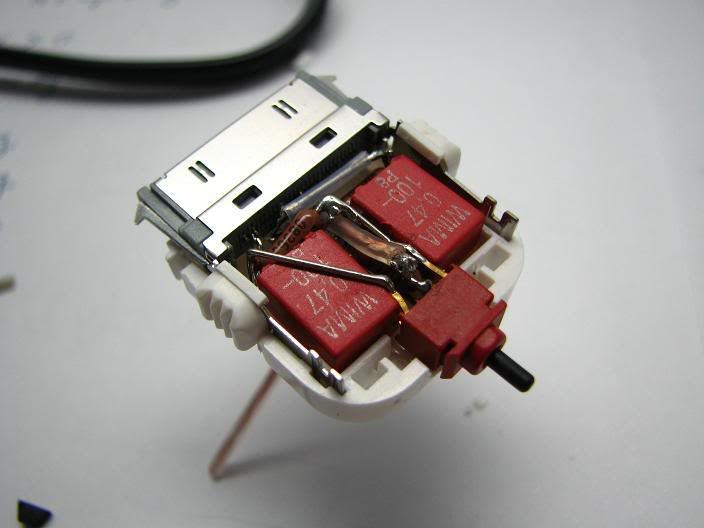
experiment four
imods 5g/5.5g video
sending the lineout to headphone out. there are several reasons for doing so.
-no need for lineout docks
-near zero risk of wires breaking loose to the pads
-right angle to right angle interconnects to external caps, resulting in simpler and compact implementation.
the pads for doing this should be the large yellow caps underside of the clickwheel connector.
----------------------------------------------------------------------
hope to hear from you ambitious diyers out there.=)
-
looks like a good all in one package, less hassle. note u also have to get a rather good optical cable. stereo should have some.
there is stereo in woodlands causeway point, and there is also another one in dhoby ghaut plaza singapura.
-
haha, yup, its quite a hit n miss with the woodie amp since there is very little reference on the internet for the digital volume control.
*I cant edit the 1st post already since there is too many pictures*

-
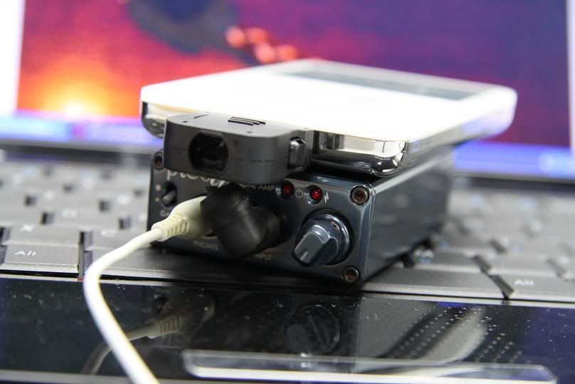
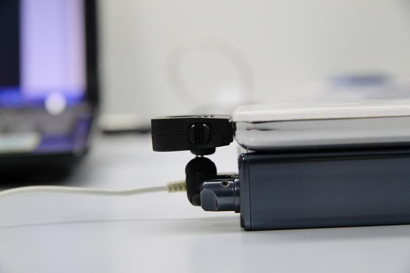
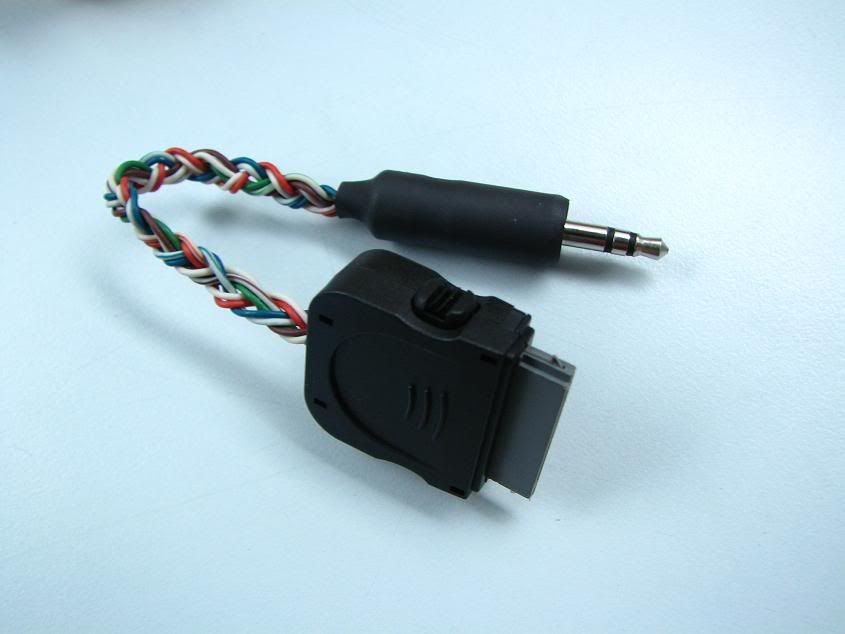
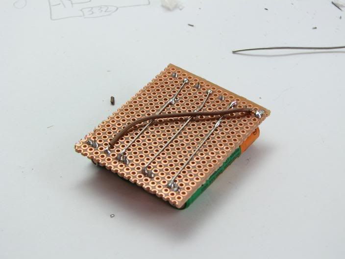
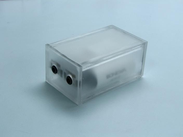
world's first crossfeed low profile lod
Pictures
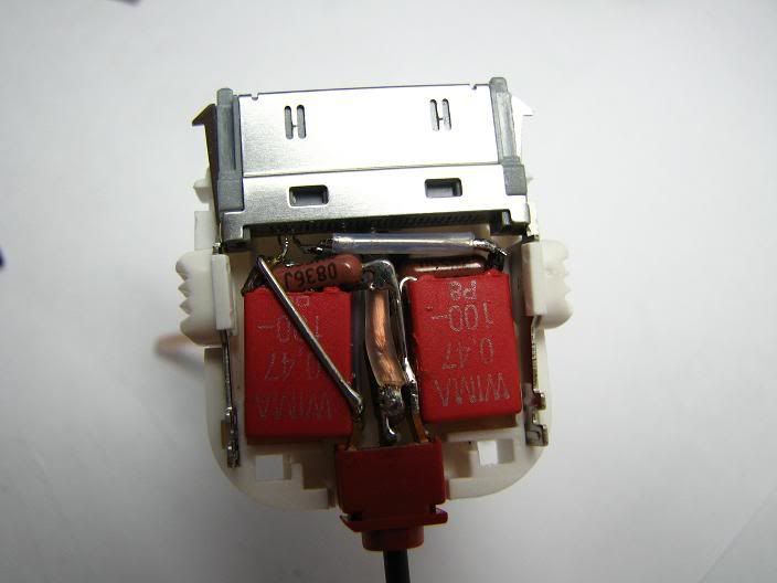
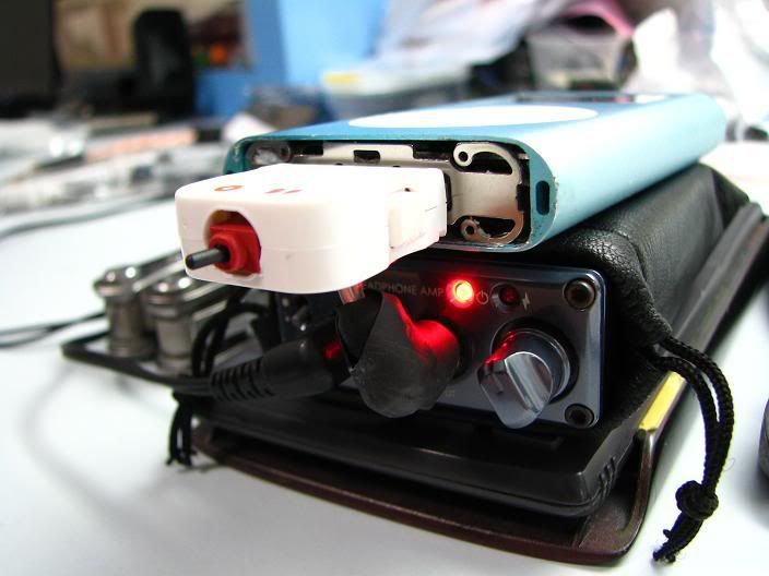
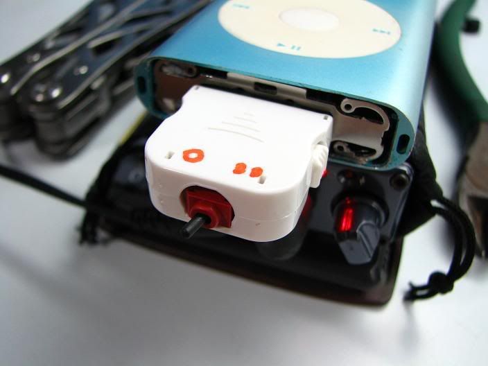
switch positions
left is crossfeed, centre is mute, right is normal.
cable is mogami neglex copper.
-
buy a replacement harddisk online and get someone to replace for u. the ipod classic 6th gen/ 7th gen are very hard to open.
if u cant go online, try to get a cheap spoilt ipod of the same kind and transfer over.
on another note, it may not be the harddisk at fault here, since the ipod would definitely boot up, display turns on and tell u the harddisk has a problem, with a sad ipod face or folder.
-
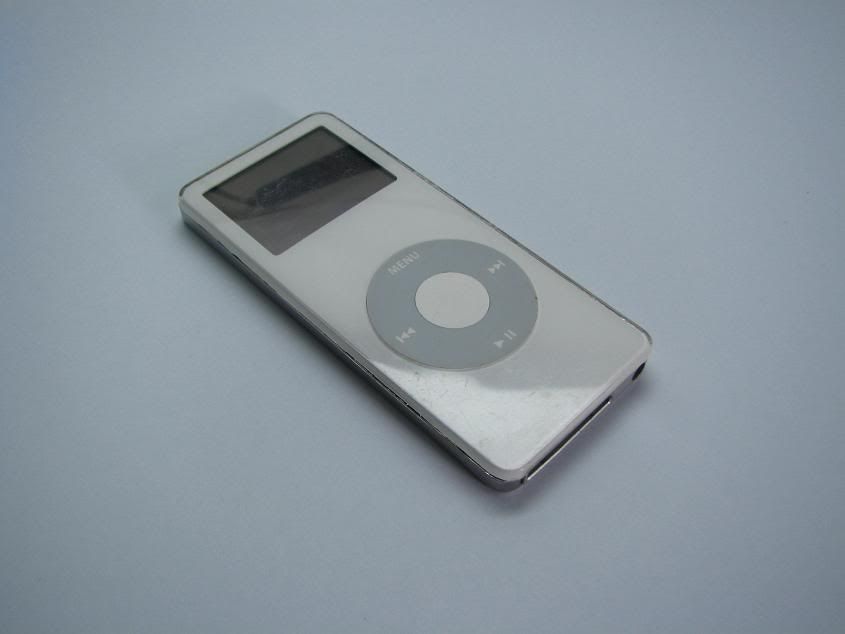
thats not a nano. its an ipod mini. minis uses a compact flash/ microdrive for its memory storage.
-
i agree on the aesthetics. i plan to refit the pimeta in a nicer metal casing and the engravings as well.
walnut is rather hard to cut! and where to buy them?
theres another amp that i'll been working on for the past 6months. i'll post once its completed.
-
not much anyway.
from top
1) My first lod
2) Mogami copper lod
3) Jenalabs lod + ic
4) Unknown copper from japan rca to mini
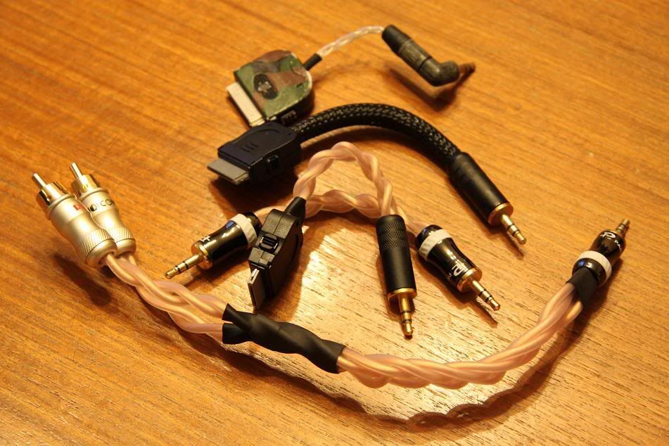
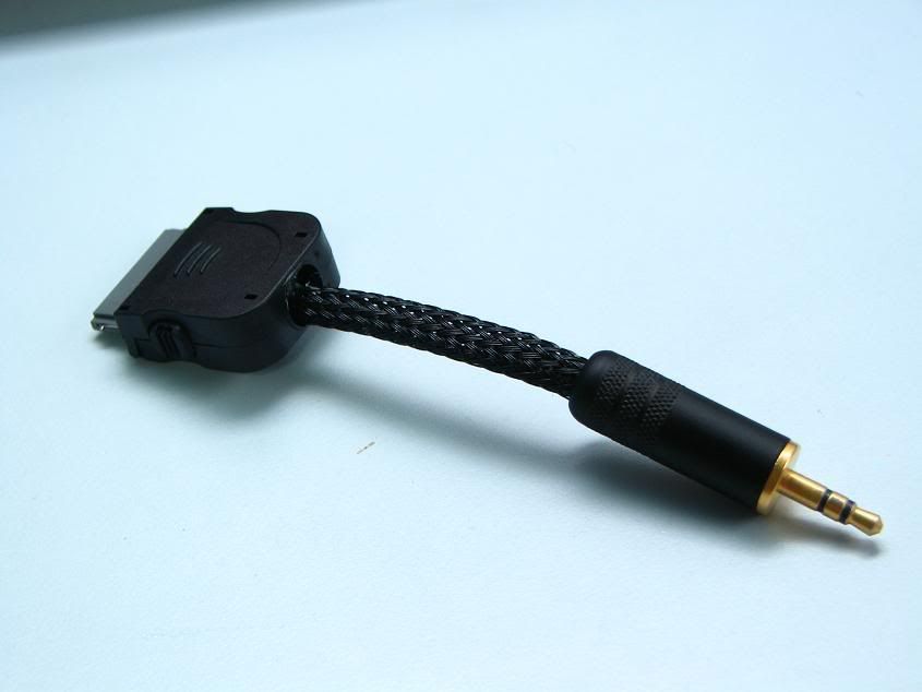
and heres a low-profile mundorf
heres one made with cat5e lan cable
heres one with sleeve, mundorf and blackgates
-
i made a couple of lods using jenalabs and mogami 2534, and another low-profile lod.
-
This is thread to consolidate all of the audio DIY i made so far.
Please keep your comments related to the thread to make it easier to read.
List
1) Pimeta
2) Woodie
3) iMods
Reserved
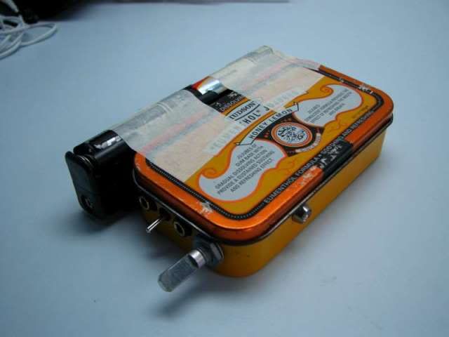
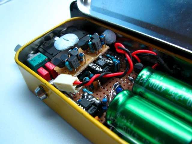
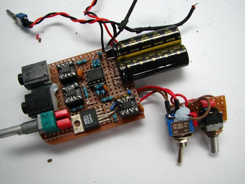
The PIMETA
pictures speak a thousands words, so pics first!
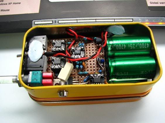
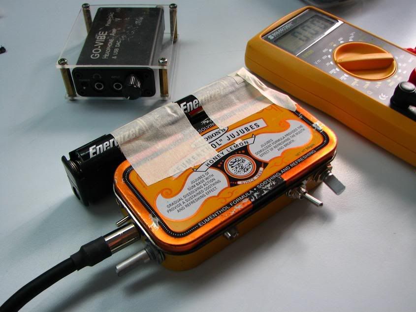
yes its in a very big candy box
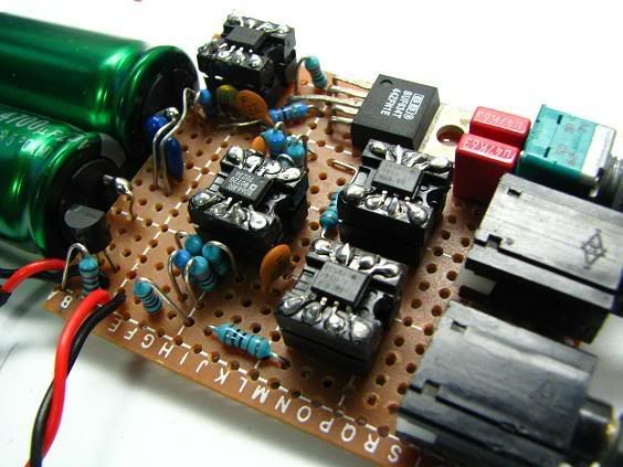
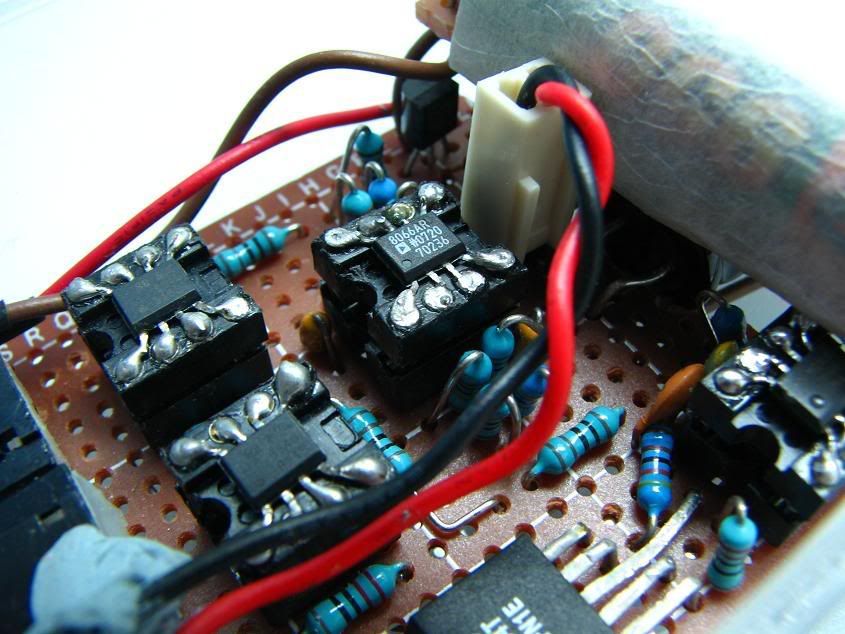
close up on the opamps, AD8066 and BUF634U buffer
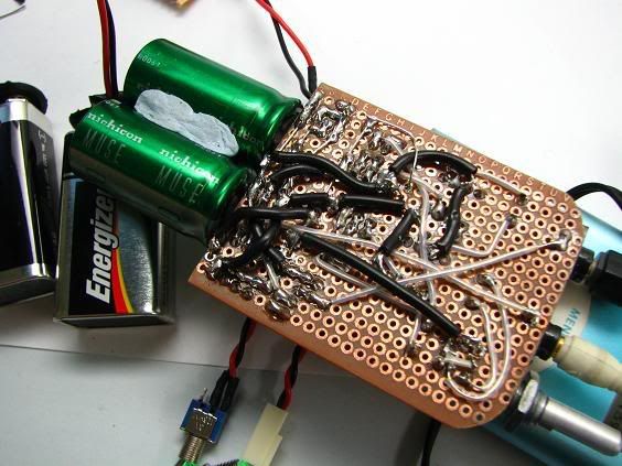
Its a nightmare to wire it up! Copper wires for power supply, 0.5mm silver core wires for signal lines.
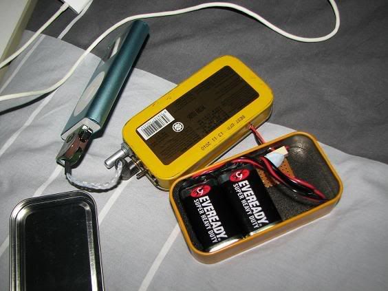
the other candy box, 2 evereadys
stack them up! power lines from the side.
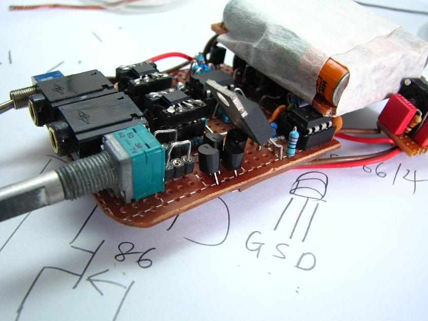
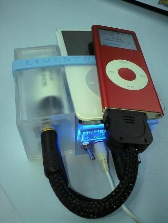
my rig, rubber banded and hand carry! brought it on mrt/bus.
another shot, my cmoy on the background.
heres the schematics
specs:
Power Supply: 2x 9v Eveready, Nichicon Muse FX series 4700uf x2 , TLE2426 rail splitter, 4.7 tantalum cap x 2, 0.01 NPo ceramics x 6
Opamp : 2 x AD8066 on dip adapter, BUF634U on dip adapter x2, BUF634T
Other stuff: ALPS RK027 50k log pot, WIMA MKS2 0.47uf, and 1% resistors.
References:
tangent's pimeta webbie
AD8066 datasheet? counts as reference ?.
Sound signature:
not sure how to describe, i wld say more bass and detailed.
seems to have more effect on dynamic drivers than armatures.
its only burned in for 6hrs plus plus. battery life is short.
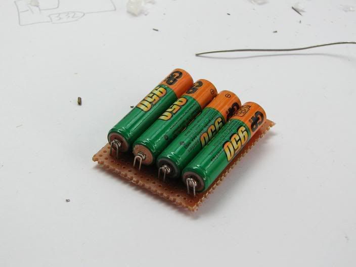
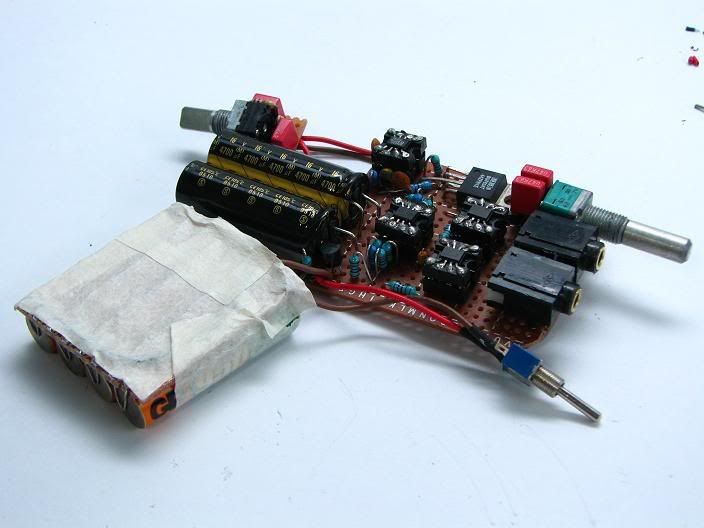
* UPDATE *
-Instead of 2x 9v batteries, 4x AA batteries are used now, they last longer!
-Made sijosae diamond discrete buffer, using bc337/bc327.
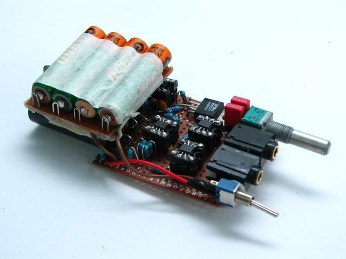
Pictures first!
The new 4xAA battery pack
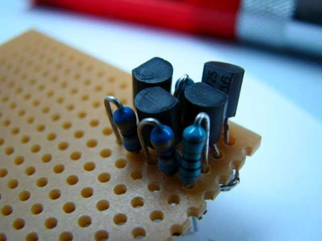
The diamond buffer, pin compatible with buf634
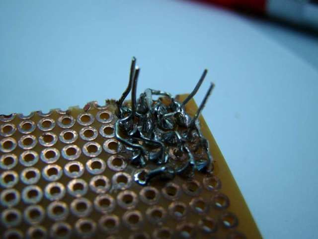
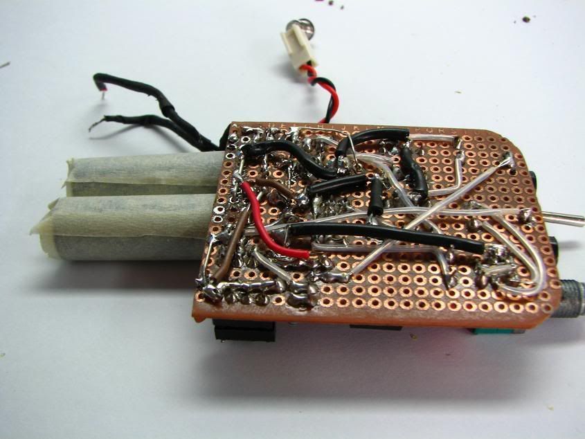
Underside! tight soldering
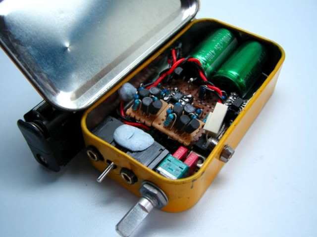
Out goes the buf634u, in goes the diamonds!
Back view, its a very tight fit in the box, a cap was in the way, bent it down flat.
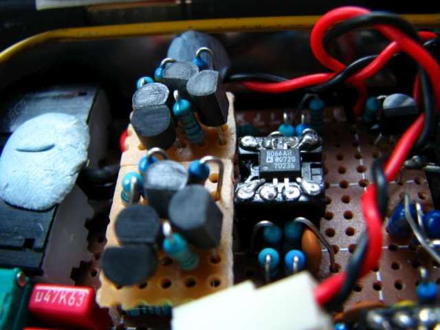
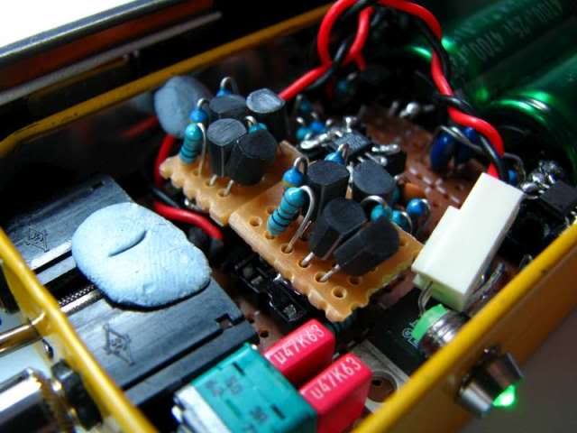
Close ups
Transistors are not matched (ie check their hfe), but bought from same shop, so should be roughly matched.
First impressions - Less clarity, more boomy, more airy soundstage.
Mesurements:
Rail to rail voltage : 5.31volts
Output Left to Ground: 1.9mV
Output Right to Ground: 5.0mV
References:
Sijosae Pin compatible Diamond buffer
http://www.head-fi.org/forums/blogs/joneeb...ax-diymods.html
*another update*
rebuilt the power supply, changed the power caps to Elna 4700uf 16v. they are more compact and space saving!
looks more neater now.
added a bass boost from PPA too!
A on/off switch for the boost, and a pot to adjust the bass.
New holes for the switch and pot.
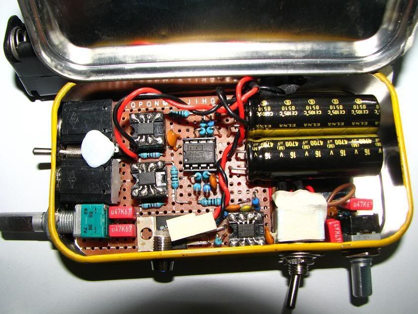
A look inside! there is practically no more space for any more upgrades.
bass boost starts at 179Hz, peaking at 10Hz with 25dB of boost.
First impressions on the sound: Bass is noticeably stronger, although its slightly muddier.
Nonetheless it makes up for the lack of bass my Q-jays has.
Notes: i ditched the transistor buffer due to rolled off highs and distortion in vocals. Should be able to remedy with matched transistors
going to revamp my pimeta casing. so watch this space!
sneak peek.
heres another sneak peek
some progress
shifted the headphone out socket, power switch now on the side
new battery pack, mounted transversely
replaced decoupling ceramic caps to smaller polyester ones.
removed bass boost switch
sockets for lineout wima caps, can be removed if using external caps.
rewired the power supply, no more thick black copper wires.
the dc offset is quite low at 2mV both channels.
acrylic casing is done, gonna drill holes tomorrow.
the sonicaps came in a few days ago...=)
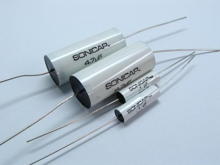
4.7uF and 0.1uF
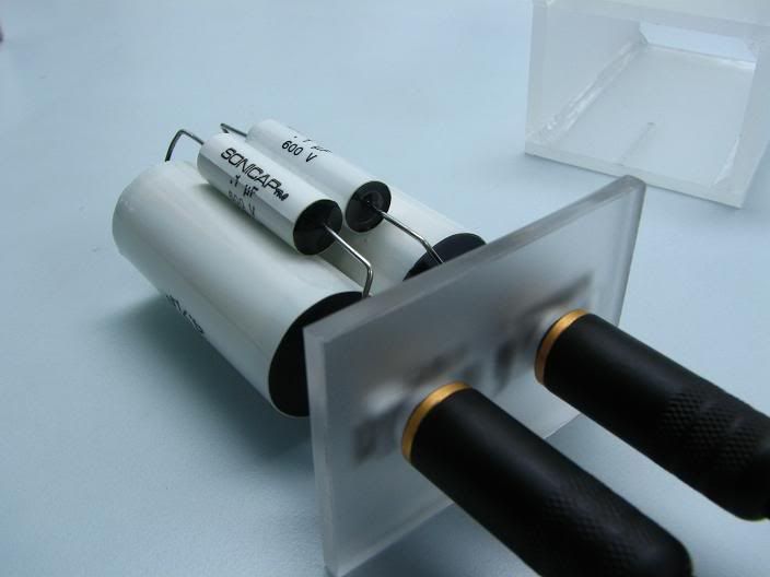
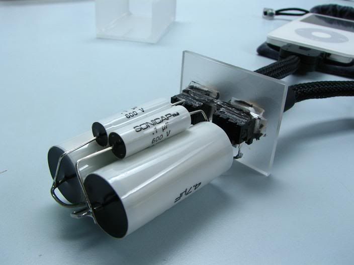
soldered onto headphone jacks
boxed up. it fits!
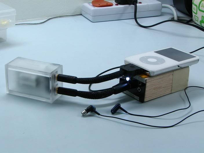
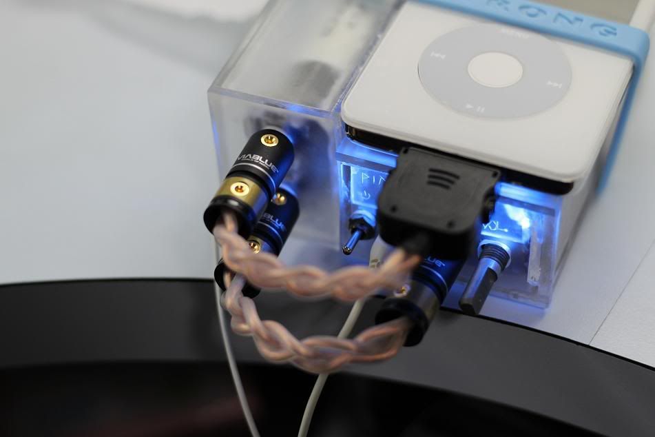
in connection! diymod 5g -> sonicaps -> woodie amp ->fxc70
shall listen to it now...=)
Just completed the PIMETA casing. I like it. i hope u guys like it too.
visual treat first...as always!
Front, perfect fit
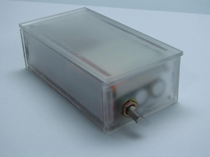
Back, bass knob
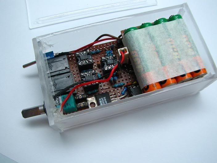
Insides
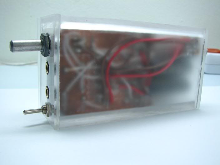
underside
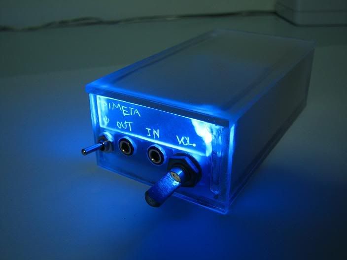
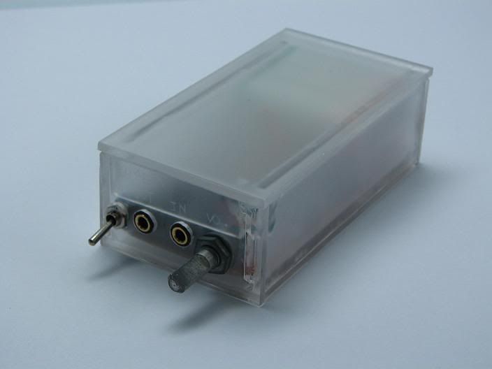
Turn on...labels for in/out/vol./power on...finally!
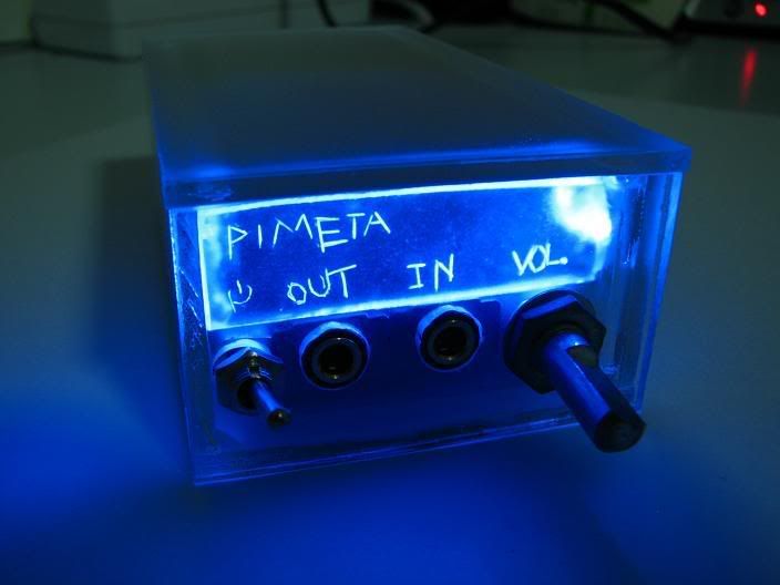
another view.
Lots of work done on the casing, phew! now to take on uni life.
Update!
bought a few opamps from farnell yesterday night. delivery came in this afternoon. super fast.
they are
-AD8656 , tested with LMH6655 as ground opamp
-LTC6241 , tested with LMH6655 as ground opamp
-LMH6655 , tested with OPA2227 as ground opamp
i also compared them to my current opamp
-AD8066 , tested with LMH6655 as ground opamp
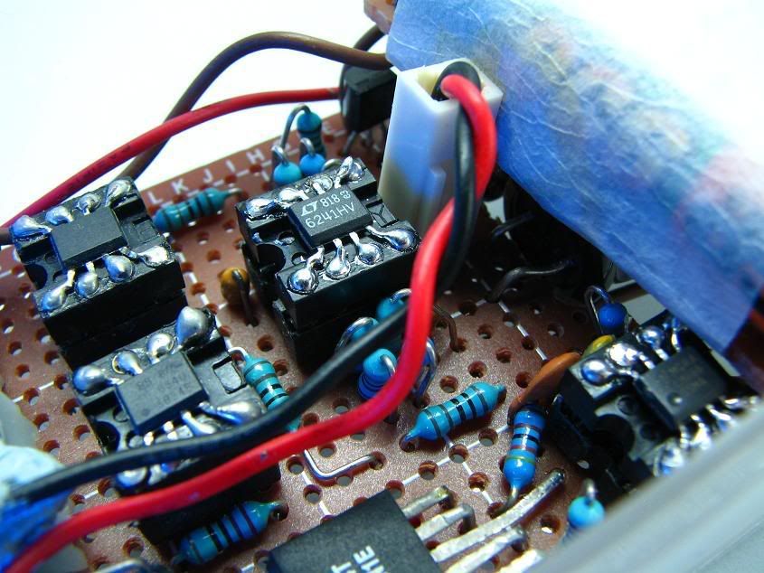
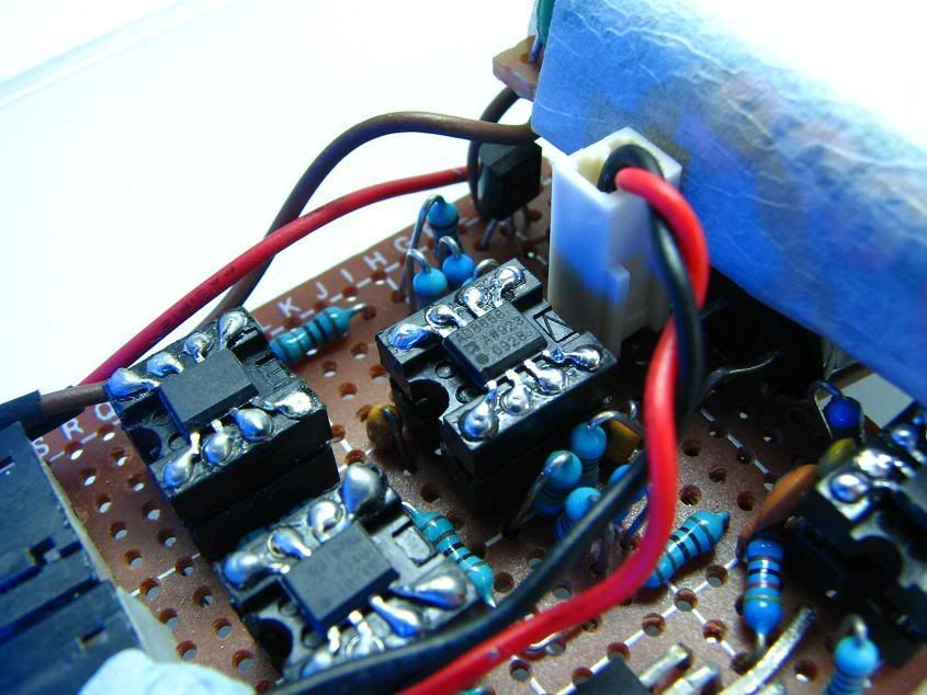
managed to solder them onto dip sockets, planted them on my pimeta and gave them a quick listen!
photos!
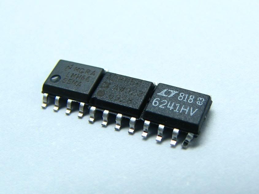
From left, LMH6655, AD8656, LTC6241HV
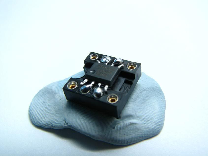
after bending and stretching the pins. soldered onto dip sockets
LTC6241
-Refined bass
-good detail
-aggressive
AD8656
-very dark opamp
-good mids
-impact bass, however is slightly muddier compared to AD8066/LTC6421
AD8066
-good low-end bass
-less aggressive than LTC6421
-rather uncontrolled bass compared to LTC6421
-best soundstage of all the 4 opamps compared
No photos for the LMH6655, it was in the ground channel in all the above tests
however i listened to it with opa2227 in the ground
LMH6655
-quite bland
-laid back
-bass sounded so so.
that wraps up tonight update. for now I'm going to use the LTC6241/LMH6655 combo. imo sounds better than AD8066/OPA2227
another update. class A biasing. using jfet cascode with 2N5484 and 2N5486 fet transistors
tested it with my earbuds. dc offset seems to still well under control. below 5mv
A few weeks ago, Ray Samuels announced a new amp, the shadow, which uses a digitally controlled volume pot.
inspired me to research on it, which i found many chips that do that. However they use a serial interface, which meant either a micro controller or a computer to control the volume.
Then came the DS1802. It uses push buttons to control the vol. Sweet.
but it came with other problems. its voltage range is very limited, from 5.0v to -0.5v, bad for AC signals.
the bottom half of the ac signal can clip.
The solution is to bias the power supply voltage, to 2.5 to -2.5, therefore allowing the room for the bottom half of the signal.
With that, i bought the chip from farnell.
Why choose a digital vol. over an analog one?
Analog pot faces a problem called channel imbalance. Left channel can sound louder than the right and vice versa. This is due to irregular tracking of the carbon strip in the pot, and prolonged use can wear out the track. Even high quality pots like the alps can face this problem.
(My alps bought from farnell was really bad, the left is much louder than the right, until the 2oclock position that it will level out)
Unlike digital chips, the resistance is controlled electronically and channel imbalance compensated using the balance pins.
thus no channel imbalance = enjoy.
Now to pair that chip with an amp. Sijosae's Class AB amp.
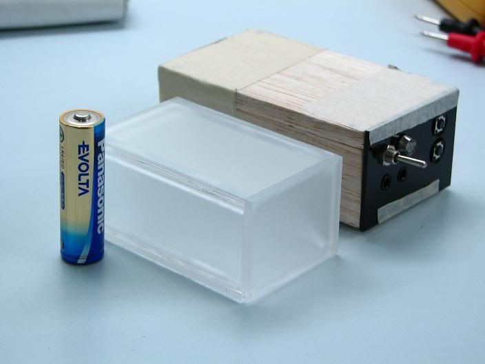
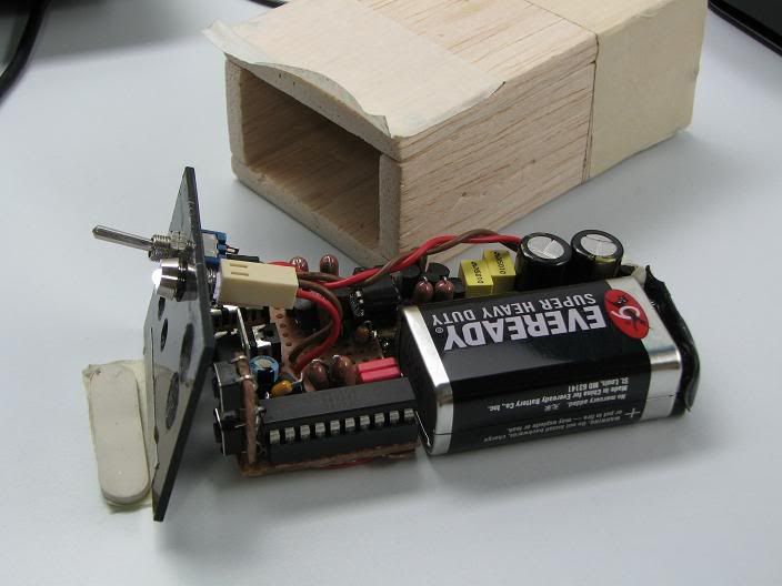
And casing...WOOD! balsa wood to be exact.
photos!
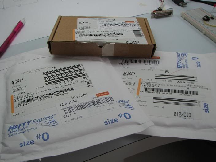
Parts from farnell, delivered free of charge.
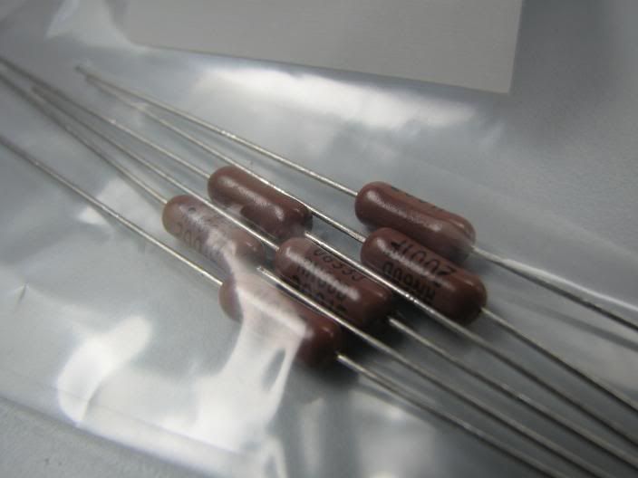
vishay dale RN60, from US!
the perfboard
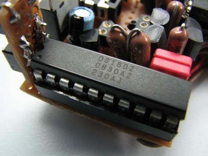
DS1802
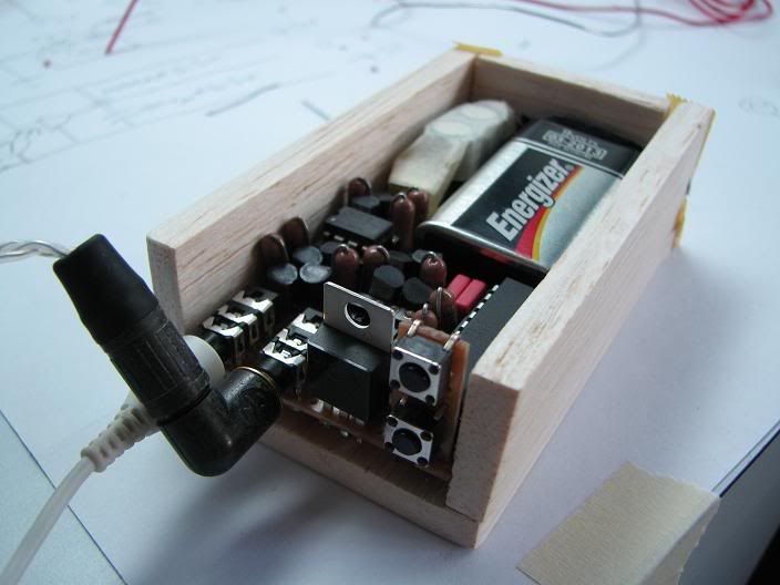
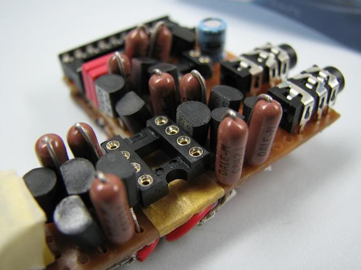
The woodie case, mini push buttons
the woodie amp, no face plate yet.
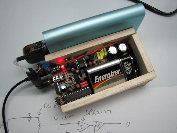
top view, its very tight.
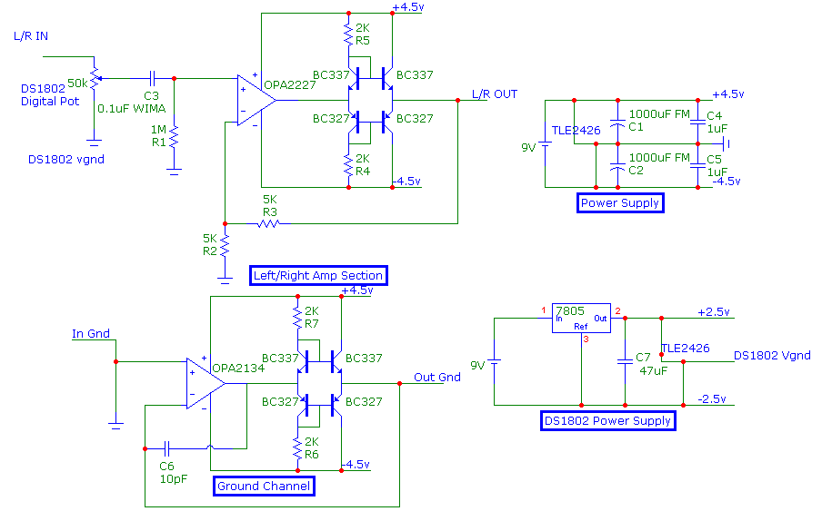
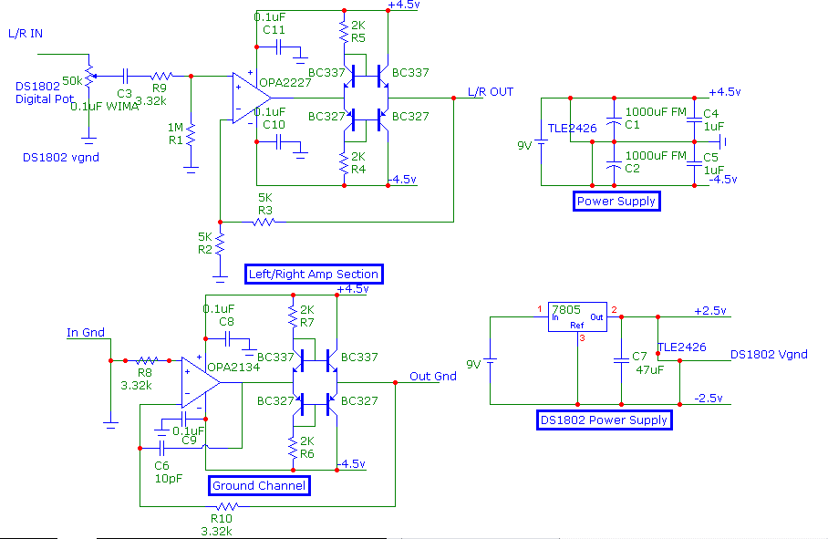
Here is the schematic, if anyone wants to try...

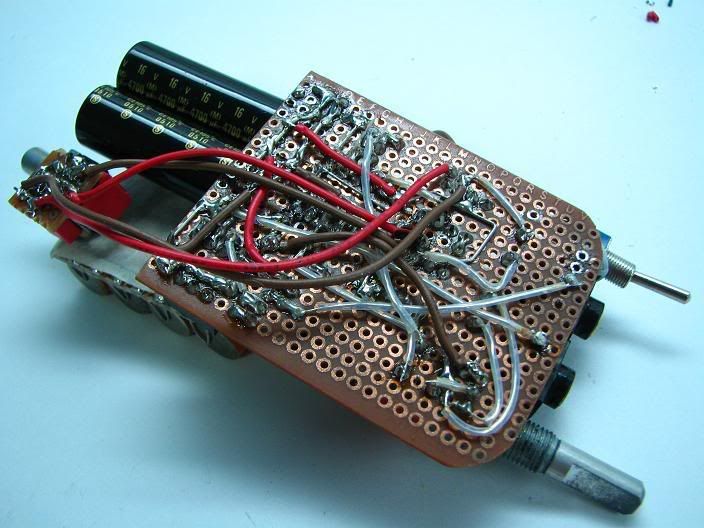
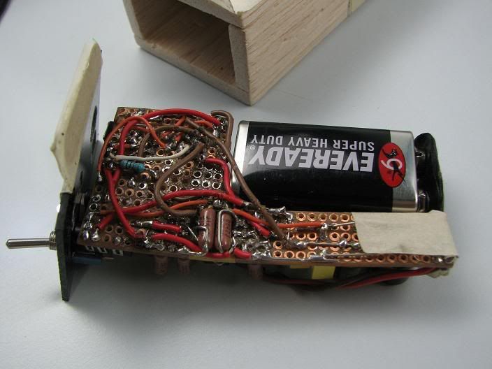
Took me 2days to get it done. There is really an insane amount of wiring under.
Those with weak stomach should turn away from the screen...
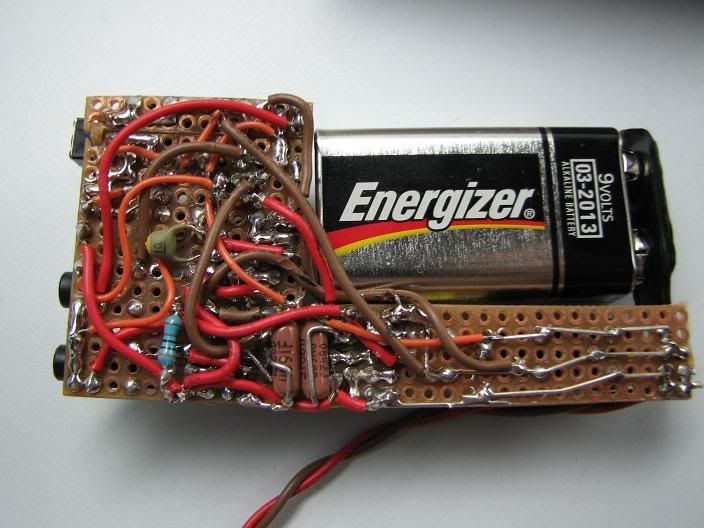
messy yes...did it work? not really.
There was a problem with the ground channel, thus i short both input/output grounds.
I'm looking for ways to solve it, or remove it entirely.
other than that...its working! the digital volume control works, pressing the buttons gives a soft click in the sound,
the sound channels are perfectly level.
More than that it sounds great!
The classAB buffers gave a strong punchy bass, while still maintaining the clarity in the highs.
mids are quite veiled however, probably due to the opa2227's signature.
its only run for an hour, a couple of 9v batteries after and it should sound better.
Measurements
Rail to rail: 8.26v
V+:4.14
V-:4.11
Left offset:2.0mV
Right offset:4.8mV
update!!!
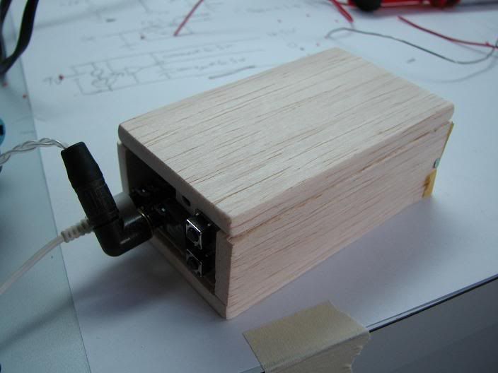
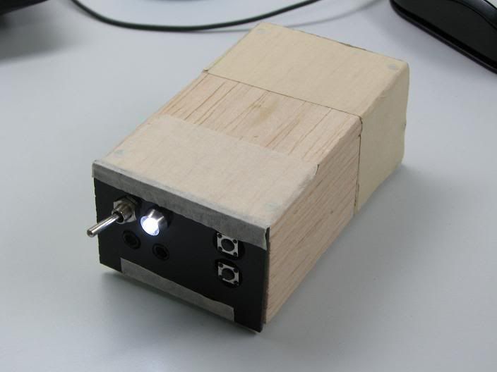
i removed the ground channel a few weeks ago. added decoupling caps and made a acrylic faceplate, nailed the top wood. strengthen with tape.
The woodie amp!
Internal shot
and the messy disastrous wiring.
and i figured out how to make the ground channel work, space constrains means i can't add it back anymore.
heres the redone schematic
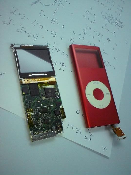
hi people. many thanks to kelvin who was willing to let me perform surgery on his ipod nano.
i present to u. the imod nano.
the victim
the same WM8758 DAC chip in the ipod video 5g/5.5g
"z" removed
soldered mundorf wires to the lineout pins. taped and secured.
the ribbon cables are a hell to put back. take note!
sounds better than nano 2nd gen unmodded. according to kelvin. many thanks man!
er. as u know. pictures first.
i present to you the diymod nano 2nd gen.
Opening it up!
A view of the apple rebranded wolfson micro DAC chip
Removing the "z"
Wiring to the freaky small line out pins
Fixed back and listening to amazing music!
Headphone jack is a hell to fit back.
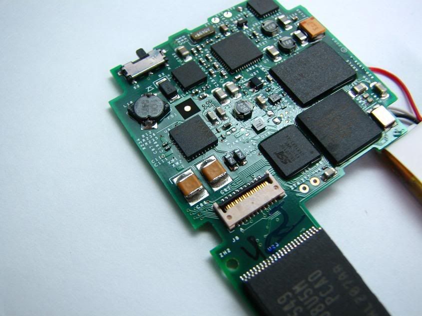
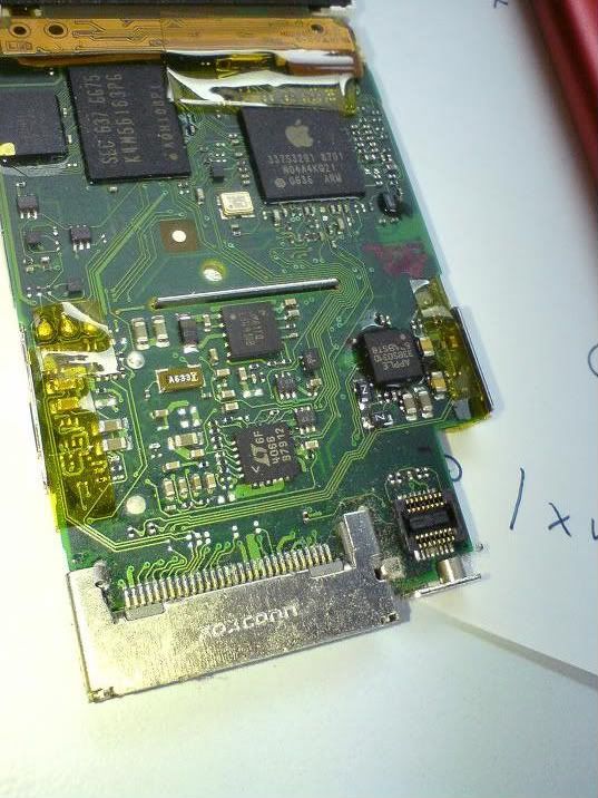
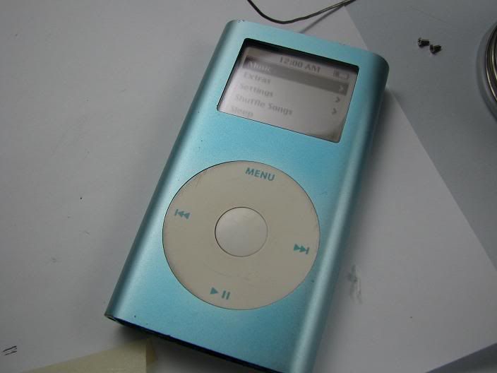
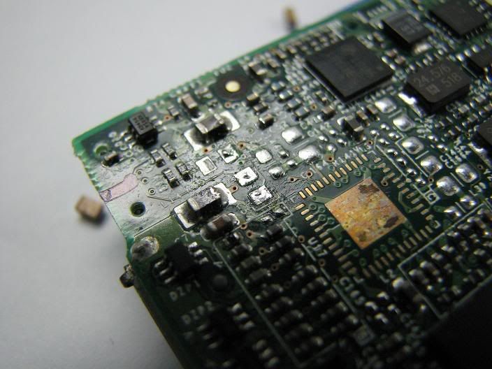
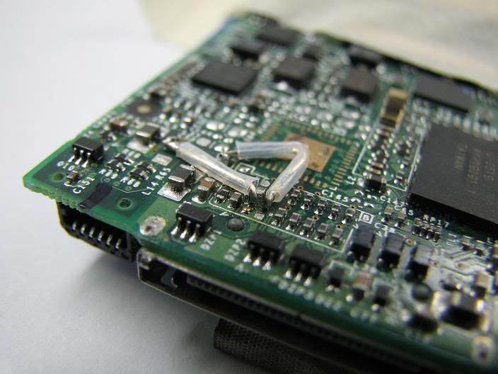
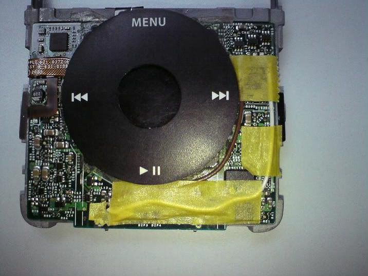
MINI 2nd gen
phew...finished it, too much strain on my eyes!
Pictures First!
The iPod mini 2g
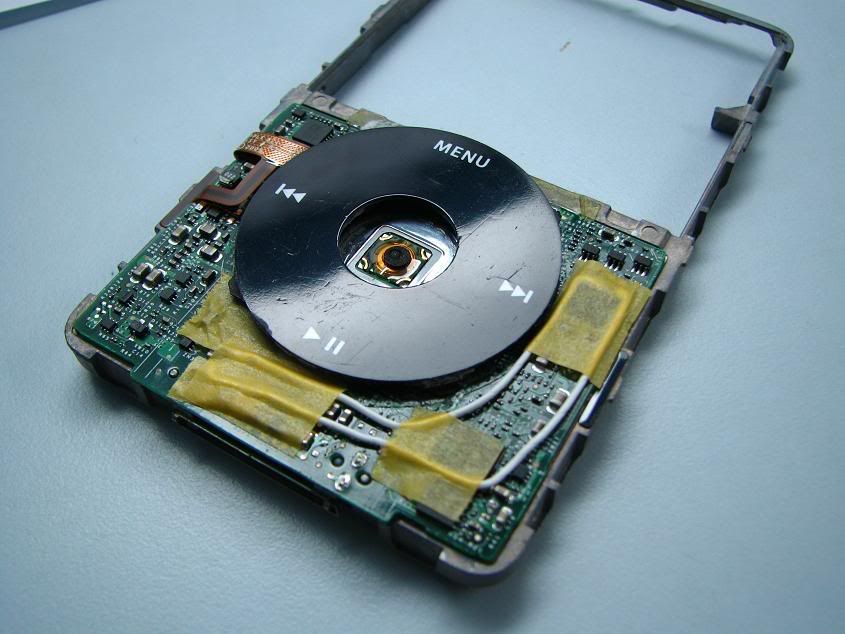
The insides
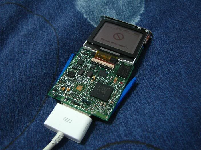
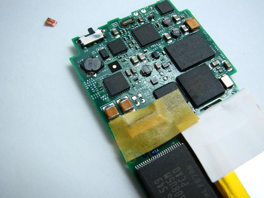
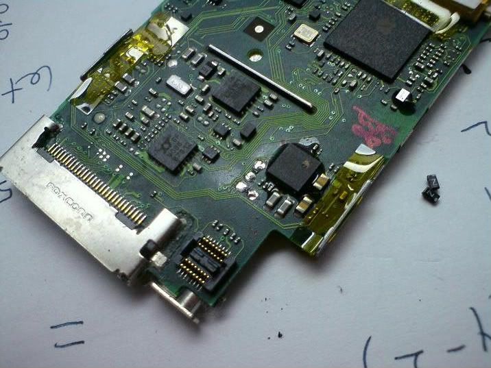
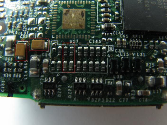
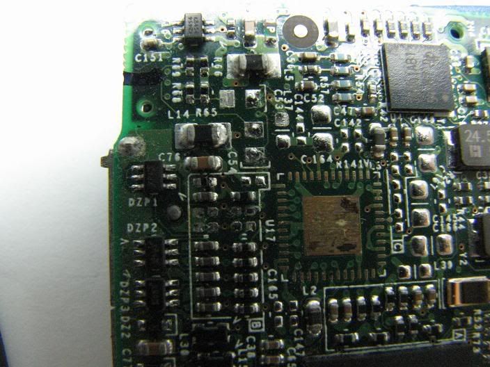
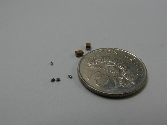
The culprits! smd capacitors and inductors
one capacitor out
Second one
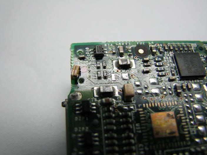
Finally the last four
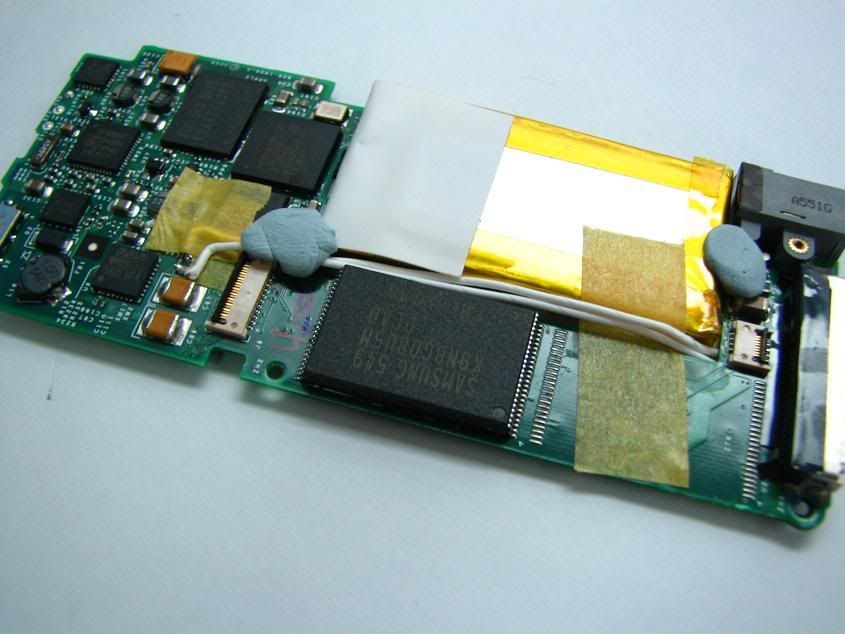
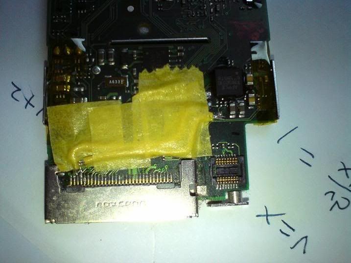
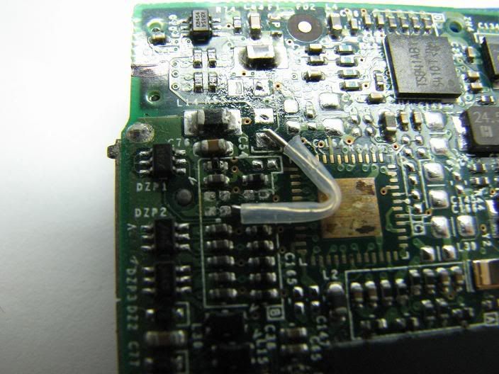
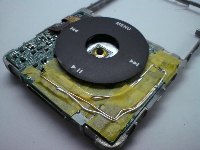
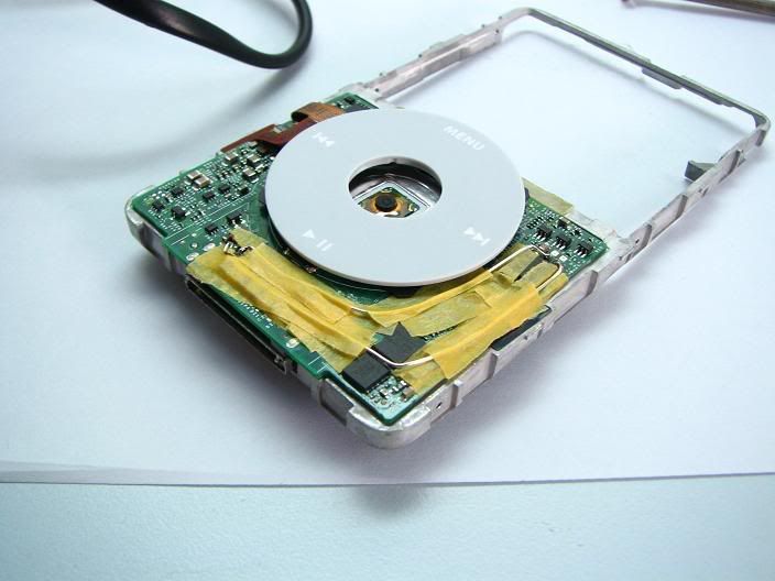
Lining up the silver core wire
blue tack!
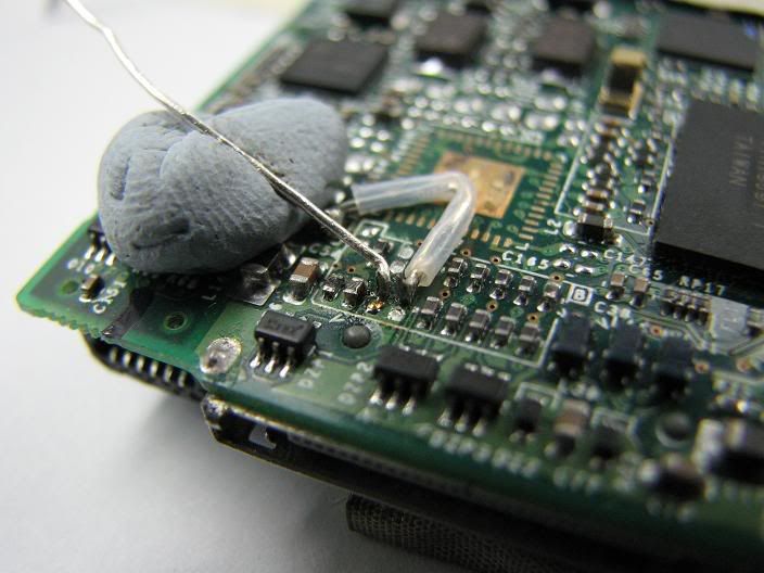
Done! neat and tidy
The tiny ones...the reason why my eyes hurt so much from squinting at such small stuff
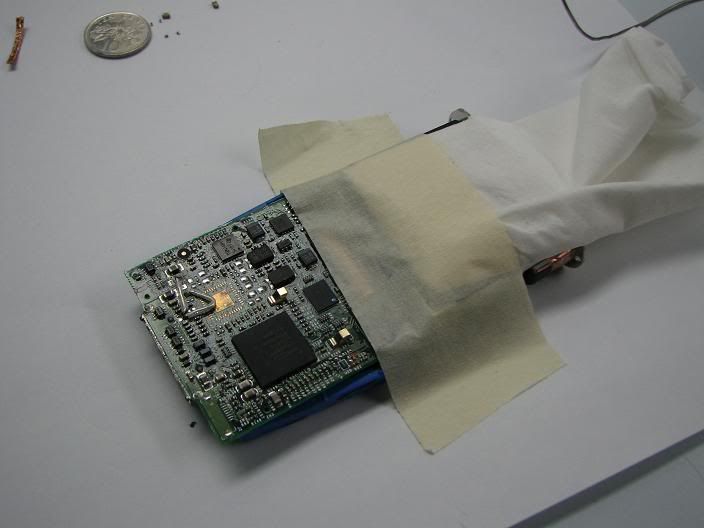
some protection for the lcd screen while soldering
the wolfsen WM8711 dac chip
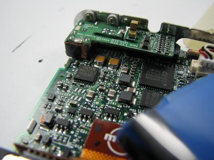
*extra* 4gb CF memory card replacing the crippled 4gb seagate micro drive
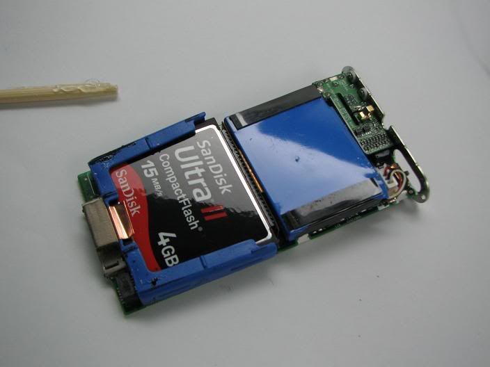
I used desoldering wick, tweezers and lots and lots of patience.
The smd capactitors and inductors were surprisingly easy to come off once u apply enough desoldering wick.
they slide off the board actually. but i think i used at least 30cm of wick.
if done correctly, should have a large dc offset at the lineout L/R to ground
mine was 1500mV on both channels.
tested with my pimeta, first impressions is that the bass is slightly more prominent.
ipod video 5/5.5gen
Hybridmod
7N silver + 7N copper
Mundorfmod
Mundorf silver gold alloy 0.5mm
Kobamod
koba silver
USBmod
usb cable
psp SQ?
in Portable Audio
Posted · Report reply
relatively low power output, but low noise. its decent