-
Content Count
35 -
Joined
-
Last visited
Posts posted by jmwreck
-
-
no problem
did you mean it on my post? if so, thank you

I hope its going to work fine

-
I have a question for the CMOY I found here:
http://diy4fun.blogspot.com/2010/03/cmoy-f...ltoids-box.html
Based on the comments, I wanted to add/alter the power supply scheme and change it into the MINI3 power and ground scheme, http://www.amb.org/audio/mini3/
Is it possible?

-
the seller MIA already. hmm i'm looking for someone who can do the repairs, will you be able to do it? haha
do you still contact the seller? im planning to build mine next week
-
It was pre built. bought it internationally from a head-fier. there's like totally no sound
really? how bout asking the seller for info. im not sure but usually it has to do with the handling of the item.

hope i can help you, since im planning to build the mini3 next week
-
bumps!!!!!!!!!!!!
whats the main problem? is it prebuild or you build it yourself?
-

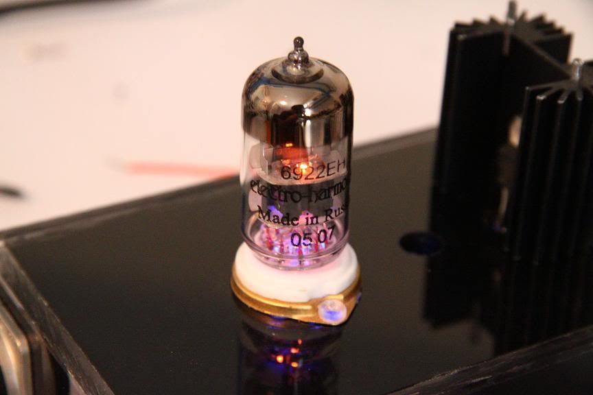
great tubes, hope you can make O2


cmoy question....
in DIY Section
Posted · Edited by jmwreck · Report reply
the mini3 schematic presented the POWER, GROUND, LEFT & RIGHT.
On the CMOY, it has POWER, LEFT & RIGHT.
So you mean, did I put the ground of the mini3 to the cmoy scheme? If so, yes I integrate it to my revised schematics. Is it correct? Thanks
-------------------------------------------------------------------------------------------------------------------------
I have a problem on the bass boost that I have added,
this is the one I found here
and the schematic is this one:
and i followed that scheme and make my own:
Left
Right
now the problem is, i dont know why it doesnt make any changes when i turn it on/off.
questions are:
1. is the original schematic (1st image) correct for bass boost?
2. are my own schemes (2nd & 3rd image) correct?
3. did i burn or damaged my "bass boost" resistor and cap?
4. it is still working perfectly right now, even with the bass boost switch is on/off, its just that it doesnt make any changes when i select it. if it was damaged (#3), does the amp still work?
5. as you can see, the values in the original bass boost circuit, especially the cap is different from the one i did? I know the fact that the higher its values, the lesser it cuts off the low frequency. but at least i can hear difference because of it, am i correct?
thanks