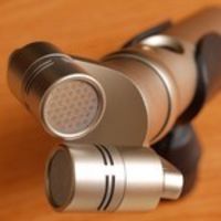
bpribadi 0 Report post Posted August 13, 2004 (edited) Here is my PIMETA like headamp. An intermezzo before building the PPA. My purpose is to make use of the AD8620 I got from AD, and also to build one decent small amp that can be powered with 2x9V battery. Here is the board layout. As ussual I'm to lazy to print proper PCB, so I'm going to use normal matrix PCB (Board layout has been modified on Aug 24) NOTE: Please don't use the previous board layout! There is a mistake on the power supply design. I have ordered the components, hopefully I can finish it by next week Any comments or correction are welcome Edited August 28, 2004 by bpribadi Share this post Link to post Share on other sites
heady 0 Report post Posted August 13, 2004 Bram, Pardon me if I am ignorant but I thought in the PiMeta, the signal ground gets a single op-amp and a buffer too? Can you comment on the merits of using the regulators instead of the TLE for the virtual ground. Of course I have no idea where to get a TLE in Singapore. Just for discussion Hey, looks nice and neat design. Share this post Link to post Share on other sites
mukegile 0 Report post Posted August 13, 2004 (edited) Heady, maybe u've read this article... here, tangent explained the limitation of TLE ... http://www.tangentsoft.net/elec/vgrounds.html Edited August 13, 2004 by mukegile Share this post Link to post Share on other sites
heady 0 Report post Posted August 13, 2004 Yeah, I did read that vground article. In the thread on Headwize, Tangent's point was that a TLE alone will not provide enough output but with an op-amp and an buffer after the TLE should be adequate. I am not advocating the use of the TLE but rather asking what is the advantages of using the two regulators method. I am no electronic expert lah, only study biology. I am listening to my 3 channel CMOY right now, dire straits. shiok man. thinking of retiring from building amps already, listening more fun. Share this post Link to post Share on other sites
bpribadi 0 Report post Posted August 15, 2004 (edited) Hi Heady, Yesterday I got no time to access internet, sorre for late reply Anyway I was quite surprised there is a dentist who likes electronic DIY Thanks mukegile for the information! From my point of view there are a couple of reasons why they use rail splitter: 1. Rail splitter such as TLE is the easiest approach, no need resistors divider, the TLE will splits whatever the supply voltage fed to it. But ground current will be limited to max 40 mA. Sufficient for most headphones, but more ground current is better. Here I use BUF634 which has 250 mA output current, should be more than enough for my PIMETA. 2. They want to use the maximum voltage from the supply. Let say if they use 15 volts adapter, they will get + & - 7.5 volts. If they use higher supply, they will get higher voltage to supply the Op-Amps. The higher the supply voltage, the better for the Op-Amp, as it will increase slew rate. With voltage regulator the disadvantage is the supply voltage to the op-amp will be fixed to a certain voltage, regardless the external supply voltage fed into to regulators. The advantage will be your amp will always sounds the same And you can accurately adjust the Vs+ and Vs-. But the advantage is, the voltage regulators is a very good ripple suppressor. So if the external power supply, let say adapter, is not giving a clean DC voltage, the regulators will clean it. For example, in PPA schematic, for every op-amp, there are some JFET transistors for the V+ and V- supply. Those transistors will give around 16 dB ripple rejection. Voltage regulators will give around 60-70 dB ripple rejection, so much cleaner DC supply for the op-amps for better sound. So that's why I choose to use voltage regulators Come on, DIY is fun too, don't retire so soon After you became more critical, than CMoy would not be enough for you Bram Edited August 15, 2004 by bpribadi Share this post Link to post Share on other sites
heady 0 Report post Posted August 15, 2004 Hi Bram, My interest is music, I bought a Creative MP3 player and also a Panasonic portable CD player both of which just could not power my Sennheiser HD490 to listenable levels. So it was to the Internet to find a reasonable solution. I know a dentist who likes building his own tube amps so I am not special nor as skilled. I think this CMOY sound good because it is 3-channel plus the virtual ground is being driven by an op-amp. And probably my Sennheiser is not that great but the combination is very listenable, the highs are now quite clean, just a little detail missing. I found the AD8620 very bass-light probably requires the buffers to sound right. I like your use of regulators for the virtual ground. Can you share where to get them and how much they cost? I was just kidding about stopping DIY This is a nice forum unlike the US sites where the people can be quite fierce. Yup, you guys are great. I am now listening to Jacinta on "Here's to Ben" and the recording is very good. I heard another SG recording Blair's Bunch which was also very well recorded. Great stuff we have right here in Singapore!! Share this post Link to post Share on other sites
bpribadi 0 Report post Posted August 15, 2004 (edited) I got Panasonic PCDP too I'm going to use LM2941 and LM2991. They are adjustable positive and negative regulators. This is the first time for me using them, ussually I use LM78xx and LM79xx for fix voltage, and LM317 & LM337 for the adjustable voltage. They are good if you use transformer (wall power), but they require significant drop out (Vin - Vout). Not suitable for battery powered amp. So I'm going to use Low Dropout voltage regulators. LM2941 and LM2991 need only around 0.5 to 0.6 volt higher at the input (maximum 1 volt for high current, 800 mA). So if I'm going to set the output at 7 volt, I only need 7.5 volt at the input. So I can use the normal 15 volt adapter to give me + & - 7 volts to power my amp. I think the output current of the 8620 is a bit low (30 mA) to be a CMoy, but probably when you add buffers like Pimeta, they will sound right. Well I'm building my Pimeta with AD8620, so I will let you know once it is done. But I don't have Senn, AKG, or other high impedance headphone. My RS-1, ATH-EW9, and Sony MDR-E888, are all happy with direct output from the PCDP. So my intention of building amp is just for fun, and for better sound quality than headphone output of my PCDP. You may try my Pimeta with your Senn to test it before you build it Edited August 15, 2004 by bpribadi Share this post Link to post Share on other sites
bpribadi 0 Report post Posted August 15, 2004 Forgot the price, you can get both LM2941 and LM2991 from Farnell at around (forgot the exact price) SGD 3.5 and SGD 4.5 respectively. Share this post Link to post Share on other sites
jtfoo 0 Report post Posted August 16, 2004 IMHO, I think you can omit the BUF634 for the rail splitter, since you're already have a +ve and -ve voltage regulator, which should maintain the Vs+ & Vs- consistently. Morever without the BUF34, you're only limited by the current the regualtor can handle rather than the BUF634. Share this post Link to post Share on other sites
bpribadi 0 Report post Posted August 16, 2004 I still need the buffer, because the supply will be from battery, or adapter which only has + and - (no CT or centre tap). The regulator will maintain the ground voltage, but not function as ground, because the current that can flow through the ground pin of the regulators is very small. So, for current going to or from the ground, we will still need buffer to do it. Thanks for your comment! Share this post Link to post Share on other sites
jtfoo 0 Report post Posted August 16, 2004 Another point I thought, maybe you want to consider using a small multi-turn pot instead of the 100ohms. I'm in the process of building a opamp base preamp, and am considering this using the pot for biasing. That way I can adjust the biasing current. Share this post Link to post Share on other sites
bpribadi 0 Report post Posted August 16, 2004 Well you have a point, but I think I'm not going to bias it to much into class A, around 1 mA is good enough for me. Some people said, the difference is not really audible, so it is just a complimentary for me. And considering the voltage drop across the biasing circuit, it already take more than 1 volt. Means, the peak-to-peak output will be reduced by it. So for low voltage supply operation, to much biasing will limit the output voltage. Unless you are using transformer, you can have much higher voltage supply, so can have more biasing current. Share this post Link to post Share on other sites
mukegile 0 Report post Posted August 16, 2004 I'm in the process of building a opamp base preamp, and am considering this using the pot for biasing. Jtfoo....what kind of topology that ur building ?... care to share ? Share this post Link to post Share on other sites
jtfoo 0 Report post Posted August 16, 2004 (edited) Jtfoo....what kind of topology that ur building ?... care to share ? Rojak, abit of PPA, abit of meta42... Biasing using PPA's method...Jung multiloop using meta42, power supply using Gilmore amp project in headwize, Edited August 16, 2004 by jtfoo Share this post Link to post Share on other sites
bpribadi 0 Report post Posted August 16, 2004 He.. He.. sorry to ask, but I'm too lazy to browse headwize. Don't mind to give us the shortcut for the power supply? Why you use META2 for the Jung multiloop? Why not the PPA one? Thanks! Share this post Link to post Share on other sites