digi01 0 Report post Posted July 28, 2006 4 parts requiring order paid at RS already... the opamp, l78l12, l79l12, and the j113 coming in abt 3-4 days time.. be careful with the TO92 packaged 78L12 and 79L12,they are not same with TO220 packaged LM7812,LM7912. Share this post Link to post Share on other sites
digi01 0 Report post Posted July 28, 2006 bleargh forgive the ugly hole will camouflage it later lazy to use my RTX cuz it generates too much powdery dust.. so used my drill and revved away FYI,I would like use sand paper wrap up a pencil to smooth the drill border Share this post Link to post Share on other sites
neutralzz 0 Report post Posted July 28, 2006 4 parts requiring order paid at RS already... the opamp, l78l12, l79l12, and the j113 coming in abt 3-4 days time.. be careful with the TO92 packaged 78L12 and 79L12,they are not same with TO220 packaged LM7812,LM7912. LM78L12ACZ and LM79L12ACZ correct? Share this post Link to post Share on other sites
neutralzz 0 Report post Posted July 28, 2006 ' date='28 Jul 2006, 04:31 AM' post='71395'] Any pics of the casing neutralzz? the iec socket as you can see i over-cut the width but its ok probably gonna find something to patch later or camouflage it.. very tight fit though.. dont think i can take the socket out easily anymore Share this post Link to post Share on other sites
heady 0 Report post Posted July 28, 2006 neutralz, where did you get that iec socket and rca? Thx Share this post Link to post Share on other sites
loop_ 0 Report post Posted July 28, 2006 Order from oversea "Taiwan". what's the website? Share this post Link to post Share on other sites
neutralzz 0 Report post Posted July 28, 2006 neutralz, where did you get that iec socket and rca? Thx the IEC was from kaichin in slt, the non-industrial one the RCAs were from martin electronics Share this post Link to post Share on other sites
Kippei 0 Report post Posted July 28, 2006 No earth ground? would it be a little dangerous... Share this post Link to post Share on other sites
neutralzz 0 Report post Posted July 28, 2006 havent soldered the earth wire outta the iec Share this post Link to post Share on other sites
neutralzz 0 Report post Posted July 28, 2006 just did up a little bit of soldering.. decided to test my fat tipped iron on this fine job.. argh!! quite a bit of suspense.. considering the cost of this board.. have to be very careful.. roar the shop i went to for 1% caps were out of 11k, no choice decided to series a 10k and a 1k.. i use quite a lot of soldering grease to ensure maximal wettability.. cleared up the mess with a piece of tissue which explains that white bit stuck.. thank god it was wonder solder.. with grease it becomes very wettable so i just need to let the solder flow down the wire and seeps into the hole forming a good joint had quite a bit of excess solder.. inverted the board and applied the iron to let the excess solder flow down the excess wire before cutting the excess wire bits off so far so good.. all connections intact.. tested all soldered parts for connectivity with my multi meter using other unsoldered points that are along the connective tracks.. the caps will go on after i've done most of the fine bits.. hope i dont botch them up as they are the costliest bits of this.. madness Share this post Link to post Share on other sites
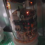
neutralzz 0 Report post Posted July 28, 2006 btw a query here for the db102g on the board the + and - are on adjacent/diagonal sides whereas those i have are like these in the picture + and - along the same side is this the correct db102? farnell only had this.. Share this post Link to post Share on other sites
chernloon 0 Report post Posted July 29, 2006 (edited) Qsilver : can give me the taiwan site that u got the nich KZ caps from? thanks Edited July 29, 2006 by chernloon Share this post Link to post Share on other sites
neutralzz 0 Report post Posted July 29, 2006 btw a query here for the db102g on the board the + and - are on adjacent/diagonal sides whereas those i have are like these in the picture + and - along the same side is this the correct db102? farnell only had this.. ookie no issue.. after looking at the schematic, and testing the db102g no issues at all. just threw on the trim pots.. maybe gonna do the rca wires tonight Share this post Link to post Share on other sites
neutralzz 0 Report post Posted July 30, 2006 hmm.. did the signal lines... had an idea actually.. decided to strip my spare belden 89259, used a penknife to slit along the insulation gently to expose the shielding and core.. removed the core from the shielding.. and slotted in 2 strands of 20 awg p-occ wires... soldered the shielding to the signal ground on one end.. i.e. rca end wrapped the teflon insulation back.. and heat shrinked the whole thing.. so its now sorta.. 1 copper shield and 2 teflon shields for the signal line.. hope it turns out well Share this post Link to post Share on other sites
neutralzz 0 Report post Posted July 30, 2006 clarification needed.. how are we supposed to short the pcs jumper area? Share this post Link to post Share on other sites